|
|
|
|
|
|
|
|
|
If one looks at the number of variations of structural supports used in materials handling systems and specifically belt conveying systems then it is worth considering the effects the selection of support structures have on the viability of the overall system or project.
This paper has investigated the types of structure commonly used and the effects they have on the system efficiency both from the economy of cost and the operational serviceability.
The types of structures used to support the elevated technological conveyor structure are shown in the following figures 1 to 6, the structures are typically denoted as:
|
|
|
|
|
|
|
|
|
(Overland structures also play an important part of this paper and will be included later)
Each of these structures can be found at plants around the world often selected for what is considered the ultimate or only acceptable structure for either the environment or the material being conveyed.
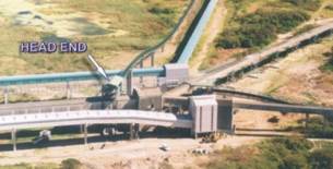
Also these structures can be found within a radius of 100m at a plant in Southern Africa, refer picture figure 7. Suggesting that because of the variations in products being conveyed at this particular plant there is a need to carefully select the correct structure for each and every application.
This is considered as good engineering application and at face value cannot be faulted, however on what basis is this evaluation really undertaken?
Let us put into prospective the effect of the structural support on the overall cost of a conveyor system. To do this we will evaluate three different conveyor lengths commonly found in materials handling plants to-day, these being 200m, 500m and 1000m centers.
For each of these belt lengths the mechanical equipment cost per meter, (not affected by the support used), is indicated in table 1 below:
| Description | 200m Length | 500m Length | 1000m Length |
| Idlers | 27152 | 61537 | 118844 |
| Pulleys | 38361 | 42884 | 49668 |
| Drive | 58379 | 65741 | 76785 |
| Belting | 52717 | 142077 | 329742 |
| Belt Cleaning | 2709 | 2709 | 2709 |
| Technological Structure | 20969 | 52434 | 104894 |
| Take Up | 49412 | 49412 | 54749 |
| Chutes and Liners | 11463 | 11463 | 11463 |
| Cost/m | US$ 1306 | US$ 857 | US$ 789 |
The cost of support structure however will not be consistent and will not be related to belt length, (variations in belt tensions being discounted). Tables 3.2 to 3.7 gives a breakdown of the quantity and unit costs for the various structures used in this evaluation.
| Description | Quantity | Unit | Cost/m |
| Steelwork | 263 | Ton | 436 |
| Trestles | 47 | Ton | 109 |
| Walkways | 18 | Ton | 43 |
| Flooring | 1500 | Sq M | 79 |
| Handrail | 2000 | LM | 29 |
| Sheeting | 3000 | Sq M | 61 |
| Civils | 417 | Cu M | 261 |
| Total | US$ 1018 |
| Description | Quantity | Unit | Cost/m |
| Steelwork | 329 | Ton | 594 |
| Trestles | 47 | Ton | 119 |
| Walkways | 25 | Ton | 59 |
| Flooring | 1500 | Sq M | 79 |
| Handrail | 2000 | LM | 29 |
| Sheeting | 3000 | Sq M | 61 |
| Civils | 333 | Cu M | 209 |
| Total | US$ 1150 |
| Description | Quantity | Unit | Cost/m |
| Steelwork | 377 | Ton | 707 |
| Trestles | 47 | Ton | 109 |
| Walkways | 30 | Ton | 72 |
| Flooring | 1500 | Sq M | 79 |
| Handrail | 2000 | LM | 29 |
| Sheeting | 11000 | Sq M | 222 |
| Civils | 333 | Cu M | 209 |
| Total | US$ 1427 |
| Description | Quantity | Unit | Cost/m |
| Steelwork | 453 | Ton | 888 |
| Trestles | 47 | Ton | 109 |
| Walkways | 38 | Ton | 91 |
| Flooring | 1500 | Sq M | 79 |
| Handrail | - | LM | 0 |
| Sheeting | 16000 | Sq M | 322 |
| Civils | 333 | Cu M | 209 |
| Total | US$ 1698 |
| Description | Quantity | Unit | Cost/m |
| Steelwork | 99 | Ton | 46 |
| Trestles | 2 | Ton | 1 |
| Walkways | 0 | Ton | 0 |
| Flooring | 0 | Sq M | 0 |
| Handrail | 0 | LM | 0 |
| Sheeting | 5000 | Sq M | 100 |
| Civils | 3583 | Cu M | 2250 |
| Total | US$ 2397 |
| Description | Quantity | Unit | Cost/m |
| Steelwork | 206 | Ton | 299,4 |
| Trestles | 46 | Ton | 109 |
| Walkways | 1 | Ton | 2,6 |
| Flooring | 10 | Sq M | 0,5 |
| Handrail | 20 | LM | 0,2 |
| Sheeting | 1200 | Sq M | 24 |
| Civils | 278 | Cu M | 174 |
| Total | US$ 609 |
The overall costs depicted in tables 3.2 to 3.7 are summarized in Table 3.8
| Description | Cost/m |
| Dog House | US$ 1018 |
| Open Gantry | US$ 1150 |
| Partially Closed Gantry | US$ 1427 |
| Totally Closed Gantry | US$ 1698 |
| Concrete Gantry | US$ 2397 |
| Triangular Gantry | US$ 609 |
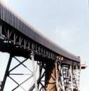
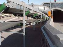
Probably the most common structure found for the support of belt conveyors both at ground line and elevated, The “Dog House” structure is considered to be the most economic. However it cannot be considered to be an environmentally friendly structure being susceptible to wind, rain and spillage from both the trough and return strands, and this structure has also been considered as an excellent amplifier of sound from belt and idlers.
This structure does not lend itself to ease of maintenance as the access to idlers on the sheeted side is very difficult requiring all maintenance to be carried out from one side only, this feature has been addressed in some instances by introducing variations to sheeting lines by moving the sheeting away from the structure.
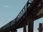
This structure is used where excessive spans between trestle supports make the “Dog House” inefficient and in the case of high lift conveyors, (> 30m lift), where serviceability, (safety), becomes a major consideration. As with the “Dog House Structure” it cannot be considered to be an environmentally friendly structure again being susceptible to wind, rain and spillage from both the trough and return strands.
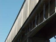
This structure addresses the shortfalls of the “Dog House Structures” providing reasonable weather protection and excellent serviceability in all instances, this structure is however susceptible to the same spillage problems as the two preceding examples and therefore cannot be considered environmentally friendly.
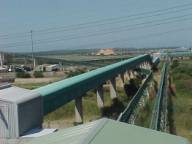
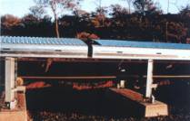
Developed to address the shortfalls in the partially closed gantry here the conveyor is totally enclosed on all four faces including the floor, even the smallest of gaps are closed to prevent animal and bird entry.
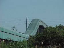
This structure can be considered the ultimate in structural support for belt conveyors also the sheeting lines and configurations are such that it can be esthetically pleasing to the eye, refer figure 8.
However again for materials with high fines content although the material spillage does not contaminate the environment there is a tendency for the dust to coat the inside of the gantry requiring periodic wash down often subjecting the structure to corrosion problems.
This may be considered the ultimate in constructions offering the full advantages of the closed gantry and not being subject to the problems of closing small gaps and eliminating the corrosion problems completely.
It does however have very limited applications being suitable for high budget, low lift conveyors where such constructions are possible and not subject to construction program constraints.
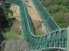
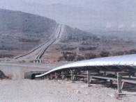
This structure takes it lead from the extensive developments of large span architecturally pleasing structures such as roof structures, refer figure 9.
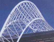
Using the high strength of pipe structure this is approaching the optimum design of low cost high span and lift solutions.
Like its own development however, it requires a re-look at the way conveyors have been built in the past and specifically the support structures for the idlers and the way the mechanical components are maintained on the conveyor structure.
However it does open the door to its use for all types of conveyor including in some instances to the use for long distance overland conveying, (to be discussed later in the paper).
Each of the above structures can be considered as optimum for the vast number of different applications associated with materials handling plant. However to really understand and select the optimum solution one needs to consider the following:
What is the material being conveyed
What is considered an acceptable belt speed?
What duty will the structure perform, (Span, Lift etc.)?
What are the environmental constraints and
What are the corrosion considerations?
The conveyed material is instrumental in selecting the correct gantry construction, consideration being given to included fines in the material, lump size and flowability.
When making this analysis, the belt speed must also be considered, giving relevance to the effect that belt width and vibration has on the selection of structure and specifically span between gantries.
The belt speed effect specifically relates to the creation of air born dust being skimmed off the surface of the material. As speed increases both air velocity and idler vibration agitate the fines and lift them up into the air to be deposited onto support steelwork and flooring and where gaps are present in the gantries the dust is deposited into the surrounding environment.
From these considerations the correct gantry selection is normally obtained giving a basic result that dusty material is fully contained in the enclosed gantry and materials less susceptible to dusting carried on the open conveyor structures.
Here as mentioned previously the spans of gantries and the lift requirements form the most critical aspects as serviceability related to component maintenance must be considered. The need to make the structure safe for maintenance is considered as the deciding feature.
Covered in the above description of conveyed material, this is not always treated as important and is often disregarded in environments where spillage is not considered a factor. Also this is a function of cost of labor required to clean up as opposed to capital cost of equipment to make the project viable.
The process of shifting capital costs into maintenance costs although considered short sighted is a very common process offering a means of getting plant up and running for “Bottom Dollar” so that income can pay for future improvements and maintenance.
This feature basically applies to all structures and is generally dealt with under the guise of a good painting specification, however because of the inadequacies of specification or the severity of the corrosion problem, some solutions are considered extreme in the least, structures such as concrete are finding their way into the evaluation.
This solution will not really be practical especially as one needs conveyor structure, (stringers and legs), which still have to be constructed from steel. But as figure 5 indicates it is being used in some areas.
Another concern for corrosion protection, relates to the triangular gantry solution which being tubular/hollow requires its own extreme corrosion protection system, especially in coastal areas.
From the analysis conducted to date it appears that one could conclude that the designers have got it right, using the dog house or open gantry for low budget, low environmental risk consideration. The enclosed gantry for weather protection but little environmental concern and the fully enclosed steel or concrete gantries for the elimination of environmental concerns.
So where does this leave the Triangular Gantry? The analysis carried out to date will not support its use in dusty, environmentally sensitive and corrosive environments, not without a completely new approach to the total make up of a conveyor solution using refinements on the basic concepts considered to date.
However let us adopt the approach that the structure is only a “necessary evil”, often being the highest cost component of the system but never justifying this high cost because it is unable to totally meet it’s specification criteria.
Also apply this “necessary evil”, attitude to the triangular gantry with its low cost and bringing it into line both environmentally and in corrosion terms requires serious consideration; apply this same philosophy to the longer overland structures where steelwork masses often make the difference between project viabilities, one will find a totally different outcome.
In the interest of completeness and to present an argument that the overland and elevating conveyors are rapidly becoming one and the same let us review the structural requirements of an overland conveyor.
An overland conveyor should:
Minimize land sterilization
It must not allow access to people or animals.
It should not be susceptible to grassland fires.
It should be easily accessible for inspection and maintenance.
It should provide optimum road and river crossings.
It should be an Esthetically pleasing structure.
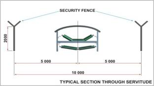
Below Figure 10 shows the typical servitude required for overland conveyor showing the access road, fencing and road crossing.
This requirement has been given little consideration in the past because often the land is owned by the mining company itself, being leased to farmers when not required and then taken back when needed for the routing of the conveyor.
What is not often considered is the fact that cutting through a farm field makes the mechanized farming of that land inefficient and has the effect that the total farm land may be considered to be sterilized, the introduction of over or underpasses will allow access but not commercial practicality; obviously a major factor in the need to sustain scarce commercial farm options. Refer figure 11.
Allowing access to the local inhabitants and animals must always be eliminated because of the danger of injury from the conveyor and to prevent theft of both equipment and material off the conveyor.
When running through farm fields, which are no longer cultivated, the grass may become overgrown and if fires start can cause damage to the total conveying system.
Obviously a major requirement of all conveyors is the need to access the total conveyor for inspections to the mechanical equipment and in the event of failure to be able to carry out basic maintenance, this function is usually carried out from a road running along the length of the conveyor.
The quality of the road depends on the terrain and environmental consideration; basically the susceptibility to wash away and erosion is critical to the actual quality of specification to the road construction.
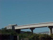
All overland conveyors will be required to negotiate some form of road, river or ravine crossing somewhere along its length. This requirement is achieved with either elevated bridge structures or underground culvert / tunnel structures.
In all instances it causes discontinuity in the access road requirements for normal maintenance and in the event that some form of mobile continuous maintenance equipment is being used, (noise / vibration detection), then this is not considered acceptable.
Considering a mining environment esthetics are only of minor significance, however in the global market where longer and longer solutions are a requirement, passing through built up areas, often linking plants to ports and harbours then one needs to introduce some form of eye pleasing solutions.
Considering overland conveyors; belt width, speed and idler spacing are considered as the most important features for the assessment of optimum design, structural options are considered by many designers to have already been taken to the ultimate.
Figures 12, 13 and 14 show some of the optimum structures; claiming masses of < 25 kg/m and simplistic fabrication and installation features.
Figure 12
|
Figure 13
|
Figure 14 |
|
The structural variations between the systems indicated in the figures relate primarily to the sheeting configurations and the spacing of the support legs, which are normally a function of idler spacing.
Reviewing these structures and applying their application in conjunction to the requirement of section 6.1 ‘The Ground Rules”, we see that all the systems are far from optimum, in fact considering the serviceability of each system over the life of mine shows major deficiencies in what has been called classical and optimum solutions.
Introducing financial considerations to each of these solutions shows up their not so obvious shortcomings and tends to justify the need for a totally new approach to conveyor structures and their applications.
Applying the same costing approach as the elevated structures and considering the structural models as depicted in figures 12, 13 and 14 as being identical we have the cost per meter as indicated in table 6.1.
| Description | Quantity | Unit | Cost / m |
| Steelwork | 125 | Ton | 108 |
| Trestles | 6 | Ton | 11 |
| Walkways | 4 | Ton | 9 |
| Flooring | 225 | Sq M | 90 |
| Handrail | 300 | LM | 47 |
| Sheeting | 1650 | Sq M | 33 |
| Civils | 417 | Cu M | 262 |
| Total | US$ 560 |
The basis of this analysis includes for an elevated road crossing factored down to assume that crossings make up 4% of all overland structures.
To compare the overland costs with the previous elevated costs we now see that the triangular elevated structure starts to compare, in fact if we now apply all the overland ground rules to the triangular structure and were able to factor in the obvious advantages of the triangular structure then we can suggest that triangular elevated structures are a more practical solution for the overland conveyor.
Considering the analysis as carried out thus far in this paper, the question must be asked as to what obvious advantages can be found in the triangular structure, which is not easily available with other structure.
To answer this question one must revert to a requirement briefly touched upon in section 6.1.4 and that is the future need will be to be able to condition monitor conveying systems, especially the longer overland systems.
With conveyors approaching the 20 km level the ability to accurately monitor the performance of belt and idlers is essential, it is also critical to understand that it is not feasible to expect a, “belts man”, to be able to observe the total performance of a conveyor throughout its length even by walking, (if at all possible), or driving with a truck along the conveyor access road.
So an alternative method of monitoring a conveyor needs to be implemented being able to perform the following tasks:
Be able to view the total length of conveyor including road, river and gorge crossings.
To be able to measure noise and vibration from idler rolls.
To be able to monitor belt drift, especially in horizontal curves.
To be able to replace damaged idlers and train miss tracking belts.
As with condition monitoring of belts, drives and pulley bearings, these features are now slowly becoming accepted not as, “nice to have”, but as essential features of conveyors. In fact installing an expensive belt conveyor without such devices and systems in place could be considered to be negligent on the part of the designer and owner alike.
As noted in section 4.6 the triangular gantry in its basic format is not considered environmentally friendly or suitable for corrosive conditions such as costal regions. However because of the obvious financial advantages of the structure and also because of the possibility that under some conditions it would be cost effective even for overland systems, then these shortcomings should be designed out of the system.
Referring back to the so called optimum structures, both normal gantries and overland; the issue of belt speed and its effect on lifting dust particles off the belt is in reality quite significant, materials such as cement and fly ash are considered as incapable of being conveyed in an open trough because of the loss of product from the belt.
In decline shaft applications where the ventilation shaft and the conveyor shaft should be the same; this is not possible because of the air born dust from the conveyor getting into the ventilation air feed.
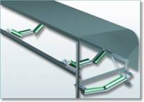
So the introduction of refinements to the total conveyor has been undertaken, including closed sheeting of the carry belt and replacement of the idlers from below the belt rather than lifting the belt off the idlers.
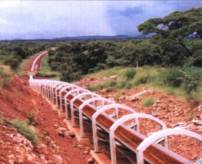
Typically this type of system is as shown in figures 15 and 16, which has been named the belt friendly structure, but it is more than that; it is also the environmentally friendly structure, confining the air born dust to the belt and allowing simple idler replacement with quick release idler frames which drop away from the belt.
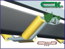
Adding a further refinement of closing the return belt in a pipe form will obviously reduce the carry over of spillage from the return belt.
Therefore including these features into a triangular gantry structure will eliminate the environmental problems associated with this structure, leaving only the corrosion aspects to be addressed in the pipe structure.
Generally to protect a pipe structure from corrosion one basically needs to seal the pipe ends. This is also possible on a triangular gantry, however it does remove one of the more unique features of the construction, that is the ability to use the structure and specifically the pipes to run cables and even carry fluids if required.
Closing the pipe ends prevents this therefore in applications where the pipes are also used to carry cables etc. a different method of protection is used. This is the subject of another paper and will not be addressed here.
Considering that the Triangular Gantry addresses all the issues put forward to produce the optimum support structure, both in-plant and overland, these are the issues still needing to be addressed:
How is the maintenance carried out?
Who or what does the maintenance?
Much of this research is presently being undertaken[1] to provide what will be considered to be the total maintenance trolley solution, being capable of viewing performance with C.C.T.V., being capable of monitoring noise or vibration from idlers, and eventually being capable of carrying out basic maintenance of idler rolls (replacement).
The time is rapidly approaching when a completely different approach will be used to evaluate the hardware selection for conveyor systems. The models shown above indicate that even overland conveyors are far from user friendly.
Considering the cost analysis results one can see that the concept of using the elevated triangular gantry with maintenance trolley has serious advantages over conventional structures and even competes with overland structures where environmental and terrain issues are factored in.
The use of the maintenance trolley concept is not new, the concept of elevated overland structures is not new. Combining them however makes the transport system both cost effective and environmentally acceptable, and these structures are now being seriously considered for long conveying systems because of its ability to be used for inspection and maintenance.
Addressing the issue of the environment and specifically spillage one can see that developing a user friendly idler bracket is the next step in the need to contain difficult materials such as cement and fly ash.
Developing the concept even further with the use of the pipe conveyor, not only can spillage be contained but also fewer transfer points need to be provided resulting in a reduction of the overall cost per ton of conveyed material.
[1] Prof. Gabriel Lodewijks (Netherlands); “Automated Maintenance”; Beltcon 12